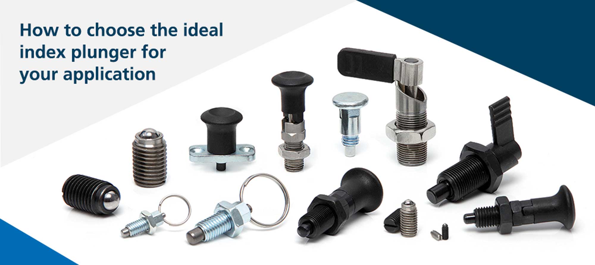
From locking, to locating and indexing, positioning and clamping, to securing, ejecting, notching and dampening, index plungers are an indispensable component in the design engineer’s toolbox. With so many types of index plungers available, how does a design engineer choose the ideal plunger for their application?
1.1. The components of an index plunger
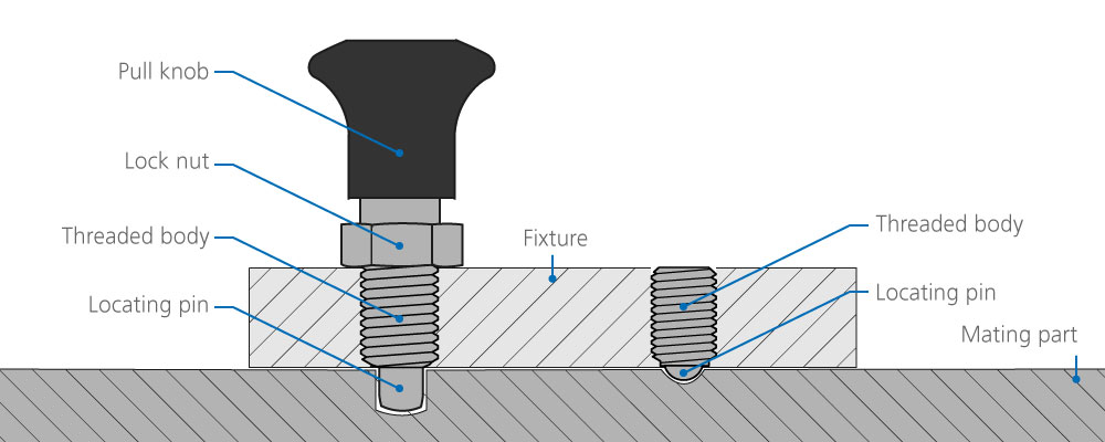
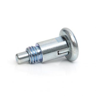
Index plungers are typically comprised of a plunger body, spring and locating pin. The purpose of a plunger is to align and temporarily lock two parts together. A notch or hole is required in the counterpart to allow the plunger pin to locate and lock.
A simple example is an adjustment rail beneath a seat which allows the seat to be moved forward, aft, and locked in place. Once the pin is engaged, the index plunger locks the adjustment rail until the plunger is disengaged, removing the pin and allowing the rail to be adjusted.
Another common application is a work-holding fixture. Thanks to the index plunger, the fixture provides secure, repeatable positioning of a component to allow a manufacturing process like machining, drilling or welding to take place with consistent accuracy.
2.1. Manual or automatic locating index plungers
When selecting an index plunger, the design engineer must identify if their application requires manual or automatic locating. Most index plungers are spring loaded, and (unless locked) will automatically push the plunger pin into the corresponding hole or notch. When disengaging, index plungers generally fall into one of two categories; plungers that disengage manually via a knob, lever or ring pull, and plungers which use a spring-loaded ball bearing and engage and disengage automatically as the plunger or the mating part is moved.
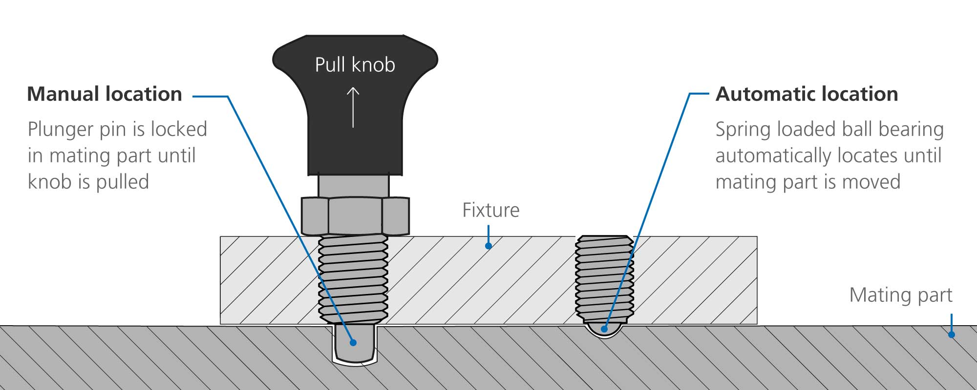
Under normal working conditions, manually locating plungers have the advantage of functioning like a lock; when the plunger pin is engaged the work piece or mating part is unable to move until the operator disengages the plunger. This makes manual plungers well suited to jigs, work-holding and furniture.
By contrast, automatic locating plungers rely on a spring-loaded ball that automatically engages and disengages only once sufficient force is applied to counteract the force from the spring which is pushing the ball into a corresponding notch in the mating part. Automatic locating is generally better suited to rapid, repeatable, high volume operation environments such as assembly lines and conveyors.
How do manual and automatic locating plungers compare?
3.1. Manually locating index plungers
Most manually operated index plungers are engaged or disengaged via a knob, lever, or ring pull. The choice between a knob, lever or ring pull is typically determined by ergonomics, price, working environment, and whether there is a requirement to lock the plunger in the open position.
What does the design engineer need to consider when choosing a type of manual index plunger?
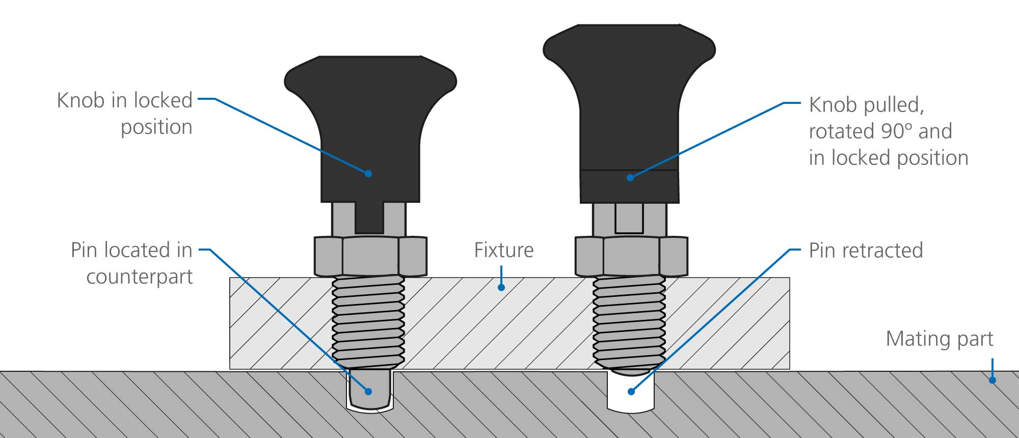
3.2. Locking position
Index plungers with locking positions allow the plunger to be locked in the retracted position. This allows free movement of the mating part without the spring-loaded mechanism re-engaging and locking the plunger in place. A locking mechanism is typically engaged via a 90-degree or 180-degree twist of the knob or lever.
3.3. Material
The choice of material for the plunger body, pin and spring is dictated by the environment where the plunger is used. If the product is regularly exposed to water or placed in hygiene sensitive environments such as catering or medical applications, then stainless construction is preferred. Otherwise, zinc plated steel is sufficiently protective.
3.4. Installation
Installing an index plunger is generally achieved via one of three means; a threaded body and corresponding threaded hole in the fixture, a flange with countersunk holes for surface mounting with bolts or screws, or an integral locking sleeve, designed specifically for mounting in thin-walled sheet material.
Jigs and fixtures generally benefit from the extra strength of a threaded installation, whereas applications where flat sheet material is processed are better suited to installation via the surface mount or flange mount.
What are the different types of manually operated plungers?
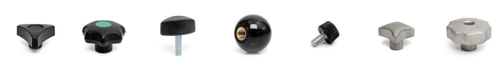
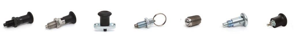
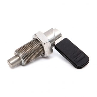
3.5. Index plungers and index bolts with knob
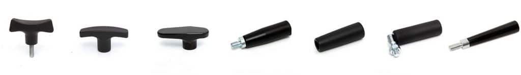
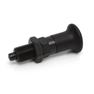
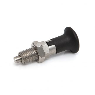
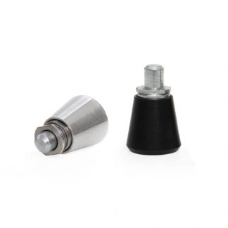
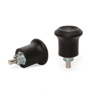
A mushroom shaped thermoplastic or metal knob is the standard implementation for most index plungers. The shape of the knob is designed to allow for a comfortable and intuitive finger and thumb grip. The knob is injection moulded from thermoplastic, or cast and machined from zinc plated steel or stainless steel. These plungers are strong, durable, and tolerate water, oil, grease and heat very well.
Rencol manufactures index plungers with knobs in a wide range of sizes, from M12 to M20 thread. We also stock ‘mini’ index plungers for use in confined spaces.
-
Model 01 IP
Spring Loaded Index Plunger
View variations
-
Model 02 IP
Spring Loaded Index Plunger with Locking Rest Position
View variations -
Model 03 IP
Index Plunger with Fixing Flange Plate & Rest Position
View variations -
Model 07 IP
All-Metal Spring Loaded Index Bolt
View variations -
Model 08 IP
Mini Index Plunger for Thin-Walled Material
View variations -
Model 09 IP
Threaded Mini Indexing Plunger for Thin Walled Material
View variations

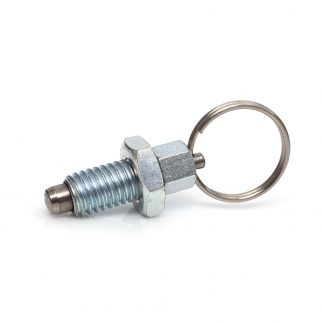
3.6. Index plunger with ring pull
A ring pull index plunger is a simple, economic alternative to a knob. These plunger types generally do not have a locking mechanism.
3.7. Cam plunger
Cam plungers feature a lever and cam shaped body. The operator turns the cam lever by 180 degrees to allow the plunger pin to be fully retracted and locked in place. Twisting the lever again disengages the lock and a spring mechanism automatically returns the pin to the extended position. These plungers have a heavy duty construction, with large levers that can easily be locked and unlocked, even when wearing gloves.
4.1. Automatic locating index plungers
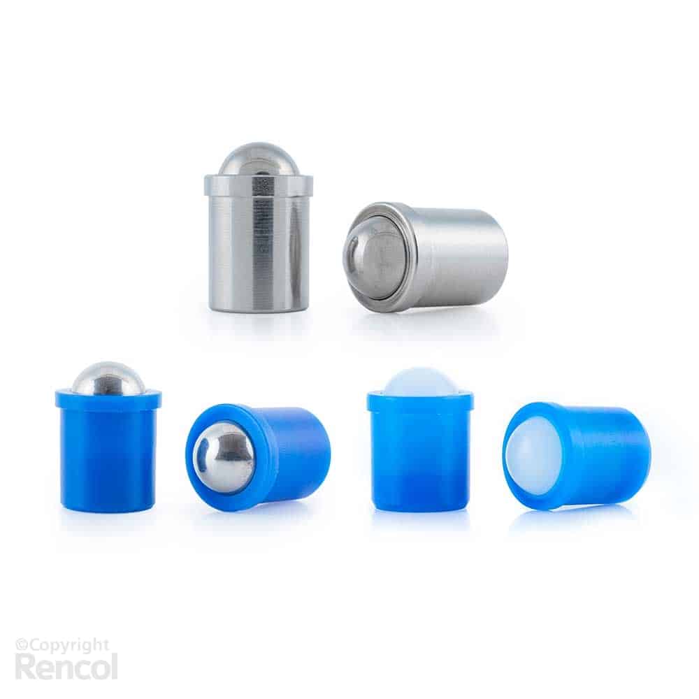
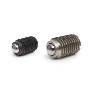
If the design engineer identifies the need for automatic locating, then a ball and spring plunger is the ideal solution. Spring plungers are simple devices and consist of just three components: a body, spring, and ball.
Spring plungers allow for accurate, repeatable, and rapid adjustments on a variety of platforms, fixtures, and furniture. The basic function of a spring plunger is achieved by the internal spring which maintains a constant force on a steel or stainless-steel ball, thereby always ensuring the ball remains in an extended or retracted position.
What does the design engineer need to consider when choosing a ball and spring plunger?
4.2. Locking position
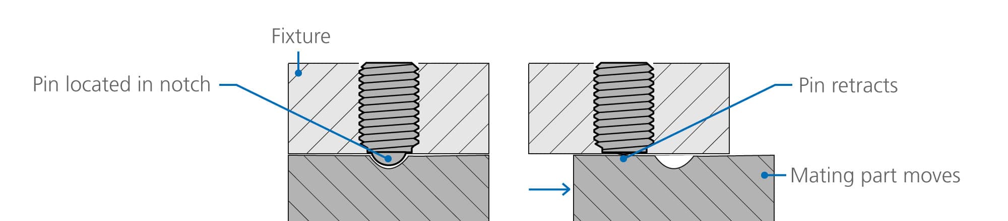
Most applications will feature a notch or series of notches in the counterpart. The ball will remain in the retracted position until it meets a notch in the counterpart, then the spring force will push the ball into the notch and create a temporary ‘lock’ until sufficient lateral force is applied to compress the spring, retract the ball, and allow the object to move again. In this case, the ‘lock’ is only as secure as the force required to compress the spring and retract the ball. If a more secure lock is required, then a manually locking index plunger is a better solution.
4.3. Installation
The body is typically manufactured from steel or stainless steel, and threaded, enabling quick and secure installation in any orientation. The ball and spring combination ensures wear on the counterpart is minimised, and maintenance is virtually zero.
Rencol produces threaded spring plungers in a wide range of sizes, from M3 up to M20. and push-fit spring plungers from 2mm up to 10mm in diameter.
4.4. Material
Spring plungers are available in steel, stainless steel, and acetal with either a stainless steel or acetal ball. These plungers are used on gym equipment, medical aids, catering equipment, conveyors, aerospace, defence, automotive.
Questions?
Email us at sales@rencol.com or call 0117 916 0090 to discuss your application with our technical team. Remember, we also offer free samples and 3D CAD downloads for our entire product range.